The goal of xR is to create a complete environment that includes real elements and virtual elements.
The disguise colour calibration is a tool for aligning how colour is represented across the system. If the colour between the physical LED panels and the virtual set extension do not match, the illusion of a single, visually-cohesive environment will be broken.
This process is aimed at reconciling the differences across all screens: it will create and apply a LUT file of the LED screens to match with the Set Extension colour. Different products across LED manufacturers will vary slightly in their representation of assigned colours - the disguise colour calibration allows them to come together seamlessly by determining the minute color differences of each LED surface, even between varying LED manufacturers.
Please note: For information on white balancing cameras, LED product and lighting ahead of the calibration, please visit the xR Hub of the disguise community portal.
-
Complete spatial and delay calibration in full.
-
Bring all lighting, LED and cameras to optimal settings and clear the stage of any physical items
-
Fill the camera frame with LED pixels.
-
Open the MR set.
-
Enter the Colour calibration menu.
-
Ensure the correct MR set to be calibrated have populated in the Settings tab.
-
Expand the Pre-Calibration tab.
The Video receive delay should be autopopulated from the Delay calibration. The camera will be automatically taken from the active camera of the MR set. For multicam setups, include all cameras to be calibrated.
-
Hit capture.
-
Step up incrementally in the Frames per test field until the colours in the preview read and saturated true representations of each colour. This ensures that all steps of each colour range are correctly captured by the camera.
-
Expand the Calibration tab.
-
Hit ‘Run’ to start the calibration. Ensure the camera does not move and lighting levels do not change.
Once complete, a mapping will be created for each combination of camera/LED screen/LUT file as determined by the elements included in the MR set object.
-
Expand the Calibrated LUTS tab to toggle on and off each LUT if needed.
-
Increase the value of the Screen Fill Factor if lighting from each LED is spilling onto the edges of the floor and affecting the calibration result. When the value is set to 1, the colour output will fill 100% of the screen.
Please note: Each physical camera will require its own colour calibration, the LUTs are switched automatically by the indirection controller when it switches cameras.
Please note: If the capture operation mode is set to “Write”, thumbnails of each colour calibration step will be written to the debug captures folder within your project. This can be useful for sending to the support team to reproduce any issues you may encounter.
Please note: For further colour adjustment to the set extension, a Colour Adjust layer can be created and assigned a CamPlate Mapping set to backplate with all cameras used for the MR transmission added as the mapping objects.
Properties
-
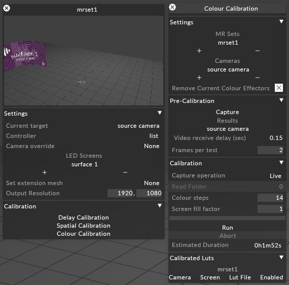
Settings
MR sets: The MR set to be calibrated. One should be selected.
Cameras: The cameras to be calibrated. All to be calibrated should be selected.
Remove Current Colour Effectors: Will remove all applied LUTs and software colour adjustments from camera objects.
-
Pre-Calibration
Capture: Clicking will capture the set number of frames on output.
Video Receive Delay (sec): The delay value of the incoming video frame that is determined in the Delay calibration process.
Frames per test: The user defined number of frames to be captured for each displayed colour value.
-
Calibration
Capture operation: Determines if the captured images during testing are archived to the debug folder of the Windows project file structure, or captured and assessed Live.
Colour steps: The range of values each colour will be captured at. The larger the number, the more tonal values of each colour assessed. Thus, the longer the calibration. A known good value is 14 but for testing, a low value can be used for a faster calibration result. For newly constructed stages it is recommended to experiment with multiple step values.
Screen fill factor: The area of the screen that is displaying colour. A value of 1 is 100% fill.
Calibrated LUTs: This tab will show all created LUT files for each camera/screen pair and can be toggled on and off using the Enabled button.